“... and everything looks worse
in black and white.”
- Paul Simon, Kodachrome
On the most basic terms, the three layers in film can be thought of as three black and white emulsions containing metal halide grains layered onto a flexible base. The layers consist of a blue sensitive layer (yellow dye), a green sensitive layer (magenta dye) and a red sensitive layer (cyan dye). The amount of dye released by the light passing though each of the layers is inversely proportional to the amount of light of a particular wavelength (color) is received from the scene, i.e. the more blue there is the less yellow dye is released by the blue sensitive layer and since these layers are on top of each other, there will be more magenta and cyan in the layers underneath. The more green there is the less magenta dye, and consequently more yellow and cyan. The three dye layers, when added together, produce the colors we see blue, green and red. These are called "color reversal films".Additive ColorBelow are some diagrams that show the basic cross section structure of film and the spectral sensitivities of the layers. The top layer is sensitive to the blue wavelengths, the yellow dye layer blocks the passage of blue light after it "exposes" the metal halide grains in the blue layer, so only the green and red light passes through, after the green wavelengths pass through the green sensitive layer they are blocked so that only red light is left.
The second layer is sensitive to green and blue light and the third is sensitive to red and blue light. Since all of the layers are sensitive to blue light a blue blocking filter layer (yellow) is added under the first layer which effectively stops blue wavelength photons from penetrating past the blue sensitive layer; it blocks blue light from getting though to the green sensitive layer (which produces magenta color dye) and the red sensitive layer (which produces cyan colored dye). Under these layers is a base and an antihalation backing which stops light from reflected off of the back of the film and going back up though the layers and provides some structural rigidity to the film.

1. Simple Cross Section
2. Color Absorption
3. Color Film Layers1. Simple Cross Section: shows the emulsion with metal halide grains, the base (which constitutes the majority of the thickness of film) and the antihalation backing.
2. Color Absorption: film cross section with the blue blocking layer and different color dye layers labeled, and the corresponding absorption curves according to the wavelengths for each of the dye layers.
3. Color Film Layers: color film cross section showing all of the layers and a description of each. Some terminology used to qualitatively describe color; Hue - the property of a color that distinguishes it from another color, i.e. red, blue or green, Chroma/Intensity - saturation, the purity or vividness of a color, Value - distinguishes the relative presence or absence of black.

4. Exposure
5. Developing6. Color Reversal, RGB sources and CMY negatives.

7. Film Sensitivity4. Exposure: simple diagram showing the exposure of film, the resulting colors and the negative image that is recorded on the exposed film. 5. Developing: diagram of the developing process with the removal of the colors, and the resulting developed positive color image.
6. Color Reversal, RGB sources and CMY negatives: diagram illustrates the separate wavelengths that are received by each of the film layers (RGB), the resulting negative images for each (CMY), and the positive image that is produced.
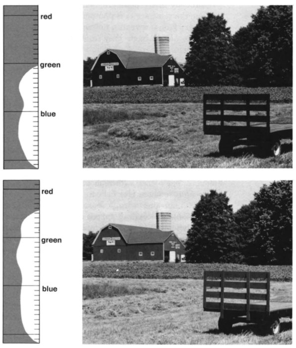
7. Film Sensitivity: shows the result of films with different sensitively to red light, note the intensity of the barn in each image.


This color reversal concept may sound confusing, and it is, but with a little practice, or brute-force memorization, you can learn it. Just remember that the colors (wavelengths) of light mix differently then the watercolor paints you used in grade school.Spectral ResponseFirst described by James Clark Maxwell in the mid 1800s, the color additive theory describes how be perceive color and how colors are created. Essentially white light is a combination of many different colors, a continuum of wavelengths organized into "bands" which we label with names (blue, green, red etc). When equal parts of each of the three major bands are combined you get white light. White light is the sum of red, green and blue.

Red, green and blue are the "primary" colors of white light. All three colors will result in white, the absence of all three will produce black.
When two primary colors of light are added together, you get a color that is brighter than either of its components.
These are the "additive" combinations:
Red + Green = Yellow
Red+ Blue = Magenta
Blue + Green = CyanBy using unequal amounts of red, green and blue light you can create new colors. Using red, green and blue, the entire spectrum of visible light can be created.

A TV monitor uses additive color. Three beams of electrons corresponding to red, blue and green are projected onto a fluorescent screen. The pixels of the screen are made of triads which are sensitive to the three colors, based on the proportion of red, blue or green light striking the triad the pixel can appear in any single color. [more graphics]


FiltersSo far light has been referred to with terms like "color", "wavelength" and "photon". These terms will be reviewed in greater detail in another module but a basic explanation is required to understand the usage of these terms here. Basically the physics explanation of what light is involves two ideas; the first is that light has wave like properties (refraction of colors in a prism) and particle like properties (the heating of a surface in the sun). The wave explanation allows for the splitting-up of the electromagnetic spectrum into colors (UV, Blue, Green, Red, Infrared, etc.) and the particle (photon) explanation allows for the explanation of the energy imparted to a surface by light of different wavelengths (UV photons have the most energy, shortest wavelength, and infrared have the least, longest wavelengths, etc).
Molecular scattering takes place in the atmosphere between the camera and the ground and has the tendency to reduce clarity. UV and blue wavelength photons that have been scattered by molecules in the atmosphere, called "diffuse skylight", enter the camera lens along with the photons reflected from scene and blur the image. Filters are used to reduce the film's exposure to these shorter blue and UV wavelengths. IR films (longer wavelengths) are less sensitive to atmospheric scattering, and are often used in conjunction with filters to increase clarity.
It is necessary to know how to read spectral response graphs. Along the x axis is wavelength in micrometers (um) or nanometers (nm) usually for visible wavelengths, and along the y axis is the percent reflectance (or absorption). Having such graphs allows for the separation of characteristic materials within an image based on the "brightness" or percent reflectance; if you know very little about an area, but have near infrared wavelength imagery, it is possible for you to "classify" certain features based only on their reflectance, and it is possible to discriminate healthy vegetation, tree types, soil/rock types etc. based solely on how bright they appeared in the image using the spectral response curves for these materials as an interpretation aid.
Below is a diagram showing the spectral response (percent reflectance) of two film types, natural color and color infrared (CIR). Notice that with the CIR film the shorter wavelengths are blocked (yellow hashed lines). This is done using filters which serve to enhance clarity by blocking diffuse skylight; the glass of the filter itself appears yellow in color (not blue). Reflectance as a function of wavelength is an important fundamental concept, the following graphics show the different reflectance characteristics for common generalized surfaces.

8. Natural Color and CIR Film

9. Generalized Reflectance Curves
10 a. Panchromatic vs. Color Infrared (CIR)

10 b. Spectral Signatures of Conifer and Hardwood Trees (Pan vs. CIR)
8. Natural Color and CIR Film: spectral response curves and the corresponding image, note the effect of the filter on the infrared photography which blocks UV and blue wavelength light improving image clarity.
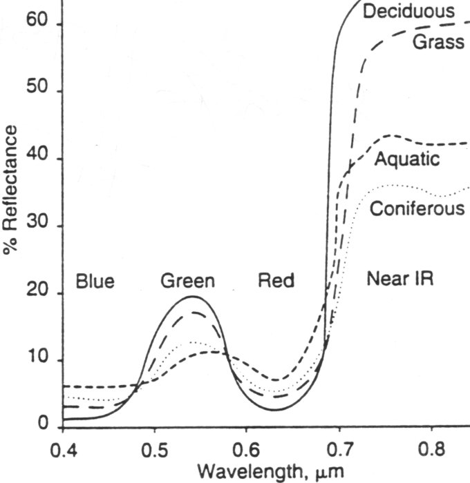
9. Generalized Reflectance Curves: graphic shows the idealized reflectance characteristics for common surfaces, note the "green blip" and the "red dip" in the visible wavelengths for vegetation, also note the strength of the reflectance in the IR wavelengths. In order for a surface to be "separable" the reflectance must be significantly different, so the further separated the curves are, for a particular wavelength, the more separable the features are.
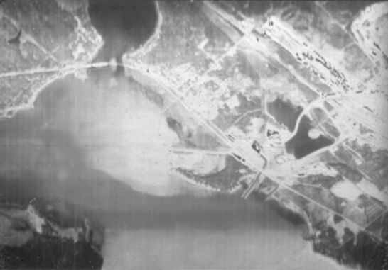
10a. Panchromatic vs. Color Infrared (CIR): this pair of grayscale images illustrates the difference between CIR and black and white (panchromatic) photography, note the differences in the trees and row crops.
10b. Spectral Signatures of Conifer and Hardwood Trees (Pan vs. CIR): This generalized plot of the reflectance of Hardwood and Conifer trees for the different film types and the corresponding wavelength ranges shows how spectral seperability depends on film type.


With filters it is possible to produce a wide array of images with different degrees of brightness, saturation and tone/color variation. Filters can selectively block different wavelengths, this enables color infrared and natural color photography to capture specific reflectance characteristics of vegetation or other features of interest. With a carefully planned and executed aerial photography mission it is possible to determine the exact specifications that are optimal for your purpose. Basic knowledge of film and filter combinations will allow you to make educated choices. Professional aerial survey firms will be able to determine the exact combination of film and filter for you. The diagrams below describe the properties of some common filters and the sensitivities of the dye layers for generalized natural color and CIR film. Notice the extended sensitivity of the CIR film, and the broader range of shorter wavelengths that are blocked by the filter.Diapositives

11. Common Filters and Wavelengths
12. Color Film and UV (Haze) Filter
13. Color Infrared (CIR) Film, Yellow (Blue) Blocking Filter11. Common Filters and Wavelengths: the number designations are used to label the filtering of certain wavelengths, these are standardized filter ratings.
12. Color Film and UV (Haze) Filter: diagrams show the filtered wavelengths and the sensitivity of each of the layers according to wavelength for natural color film.
13. Color Infrared (CIR) Film, Yellow (Blue) Blocking Filter: diagrams show the filtered wavelengths and the sensitivity of each of the layers according to wavelength for color infrared film.


What image medium type provides the most detailed image?The Developing ProcessDiapositives, also called "color positive transparencies", are the highest resolution photographic medium available, they are used for fine scale precision photogrammetric projects requiring exacting precision and interpretability. A semi-opaque glass table with a backlight are necessary, as well as high magnification viewing equipment. Diapositives are expensive to have produced (more than $100 each) and for most routine interpretation or mapping purposes they are not necessary.
Developing film is an art. Although machines process conventional film effectively, sometimes they don't work. Aerial photography is developed by hand, experienced dark room personnel are extremely valuable people because they have learned from the experience of developing hundreds, maybe thousands, of air photos what the ideal balance of tones and colors for a particular area should look like. Achieving the "best" positive image from an aerial photograph requires a good eye for color and knowledge of how to correct for certain factors like lighting geometry changes along a flightline, overcast conditions, or color hues in vegetation or soil that show-up in aerial photography as a result of the lighting geometry. It is for this reason that when a flight is contracted from an aerial photography firm that you, the client, have the right to inspect, and in rare cases reject, the final products. Aside from choosing the optimal film, filter and lens combination, the process of actually developing the positive images is very important.Type of Conventional Aerial ImageryCare in the developing of the photography is important for interpretation purposes. In some cases CIR photography may be "over developed", the red hues may be exaggerated giving the interpreter a false impression of vegetation health. This problem is especially acute with the interpretation of wetlands. Using aerial photography to map natural landscapes requires field experience, or on the ground images in some cases, to develop a sense or "signature" of what the features of interest look like. Time of year, especially in the case of wetlands, is a very important consideration. The ideal time to have a site flown may be different for different types of vegetation. Leaf-on or leaf-off photography, as well as when certain species come in to bloom, may be required. For this reason locals and experts who are familiar with the study site should be consulted prior to planning an aerial photography mission.
Aerial photography is typically available in;Color Infrared Film (CIR)
- black & white (panchromatic, grayscale)
- natural color (red, blue and green)
- color infrared (false color, black and white)
Color infrared film is often called "false-color" film. Objects that are normally red appear green, green objects (except vegetation) appear blue, and "infrared" objects, which normally are not seen at all, appear red. The quality of the film/camera, time of year, climatic conditions and how the film is developed influence how landscapes appear in CIR photos. The primary use of color infrared film is for studies involving vegetation such as wetlands mapping or ecosystem monitoring. Healthy green vegetation is a very strong reflector of infrared radiation and usually appears bright red on color infrared photographs (depending on how the film is developed). Color Infrared (CIR) uses special film, lenses and filters to capture reflected near infrared energy (sometimes called Near IR), NOT emitted thermal infrared (heat). A common misconception about "Infrared Photography" is that it is associated with heat - this is wrong. Color Infrared (CIR) photographs capture sunlight that has been REFLECTED from the surface, NOT emitted (that's Thermal IR).The graph below shows the wavelength ranges and describes an important concept for remote sensing - atmospheric absorption and reflection. The maximum reflectance from earth's surface is in the UV and Visible wavelengths, notice that the variability in the reflectance in the non-visible wavelengths beyond red is highly variable. CIR film responds to the chlorophyl in plants, green and red reflectance, as well as plant moisture content due to the structural changes in the leaf it controls (leaf thickness). Filters are used to enhance the film's sensitivity to infrared reflectance.

Wavelength Ranges Labeled and Atmospheric Transmission
Visible and IR Wavelengths, Leaf ReflectanceBelow are three images of a power plant. Wavelengths in the natural color visible (400-700 nm), photographic IR (0.7-1.3 um) and the thermal infrared (3-14 um) parts of the electromagnetic spectrum.

Natural Color
CIR
Thermal (not a photograph!)

why is my hat red?


Lines Per Millimeter
Resolution for aerial photographs is determined by a number of factors, some of which you can control and some you can't. Those factors that cannot be controlled are the weather, the air quality (dust and smoke) and in some instances the visibility of the target(s). The factors that can be controlled are the time of year, the geometry (though altitude, lens, film format) and stereo overlap. Another consideration is the film type and filters because they can have a strong influence on the resulting image quality.Ultraviolet Photography
The resolution of a camera system is measured using a standardized scheme that is based on "lines per millimeter". The quality of a lens is often measured with this quantity. Basically the "test pattern" (see below) is photographed from a fixed altitude, and the number corresponding to the smallest number of line pairs visible (per millimeter) is recorded.

Film manufacturers sometimes use "MTF-curves" (Modulation Transfer Function) on their films. The "lines per millimeter resolution" is also used to describe lens capabilities, but for most traditional ground-based photography MTF-curves are more useful than the line pairs per millimeter because lines per millimeter can be measured with different light situations. For aerial photography however resolving power is the most important consideration. Lines per millimeter will remain a standard upon which resolution is based for a long time to come.

UV wavelengths are the shortest of the normal photographic range of the electromagnetic spectrum, they can be acquired with standard black and white film as well as specialized film and pure lenses and filters especially manufactured for UV light. Filters for UV photography are glass only, film based emulsion filters do not work. Ultraviolet photography is used by crime scene analysts due to the different absorption and reflectance properties of some substances or interest. Bruises and other markings that may have been removed, or are not apparent on the skin surface, can be photographed in the ultraviolet because these wavelengths penetrate the skin slightly.Nature photographers use UV photography as well. Insects and flowering plants have been studied using UV photography. The coevolution of insects and plants has led to some very interesting patterns.
Ultraviolet aerial photography is also used to census animals in snow environments. The fur of what appear to be white animals, like the baby seals, is dark black in UV wavelengths (because their fur absorbs those wavelengths), so they contrast very sharply against a snow background (which reflects UV). UV aerial photography is also useful for identifying oil on the surface of the water. This is because UV wavelengths are sensitive to the smoothness of the water surface; oil on the water surface tends to smooth small capillary waves caused by wind, the smoother surface causes a contrast in reflectance with the surrounding water.
Below are some diagrams and images that pertain to UV photography. UV filters are used with natural color and CIR photography to screen out UV wavelengths so they do not blur the images. UV wavelengths reveal certain surface features better than other wavelengths, as is the case with salt flats.

Common UV Filters |
 UV Imagery of salt (left most image) in Angstron units (Å), 1 Å = 10^10 m). |

Right: Boat wake through diesel spill |

Right: normal photo of a white animal hide sled, and a UV photo. |